


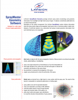
Spray Geometry and Patternation
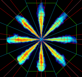
LaVision’sSprayMaster Geometrypackage extracts spray plume morphology and geometry information from backlight and light sheet spray images.Depending on the optical arrangement, the spray image obtains information about the spray pattern (radial spray cuts) or the spray plume shape and propagation (axial spray cuts).Analysis of multi-hole injectors (e.g. automotive fuel sprays) reveals geometry information for each individual spray cone separately.

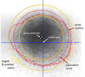
Radial spray cuts: spray patternation
shlf1314Radial cuts are derived from light sheet images in cross section with thespray axis.
spray patternarea and its equivalentdiameter
mass circlediameters according toSAE definition
centroidshlf1314position based on spray image intensity
largest and shortestradiusshlf1314of the pattern rim
plots about radial and angular spray distribution to reveal thestructural characteristicsof spray plumes

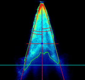
Axial spray cuts: plume geometry and propagation
Axial cuts are aligned with the spray propagation direction. Measurementsare achieved using light sheets, global lighting or backlighting.
spray cone anglemeasured e.g. at a given distance from the orifice
bent angle(deviation from orifice axis) and both
half anglesto indicate the symmetry and direction of the spray plume
tip penetrationto represent the propagation of the spray
angular spray density plotto show the uniformity of the spray
Product Information
 Spray Geometry Software

